Contact Us
Thursday 10th December 2020
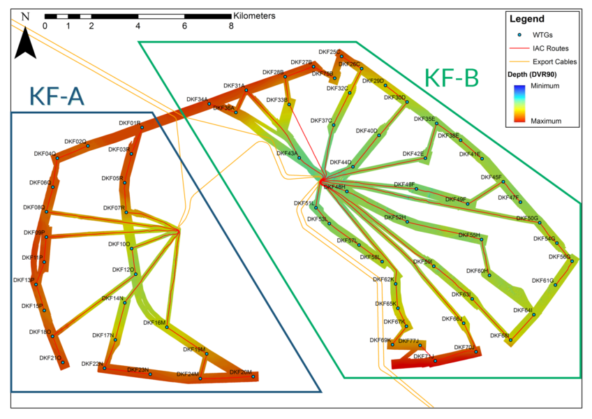
OceanIQ’s parent company, the Global Marine Group (GMG), was appointed by Vattenfall to deliver the route clearance and cable installation campaign at Danish Kriegers Flak, an offshore wind farm located in the Baltic Sea, southeast of Copenhagen. The new development consists of 72 turbines linked to two offshore substations, splitting the site into two areas: Kriegers Flak A and Kriegers Flak B. Together the sites called for a total of 72 inter array cable routes; a large-scale project requiring detailed analytical work in order to determine the most economically viable routes for the entire site.
The full scope of work assigned to GMG for the project included:
OceanIQ was responsible for performing in-depth analysis on over 6,000 boulders and a vast amount of bathymetry data in order to find the safest possible route for the PLP240, and the inter array cables themselves, between the wind turbines at the site.
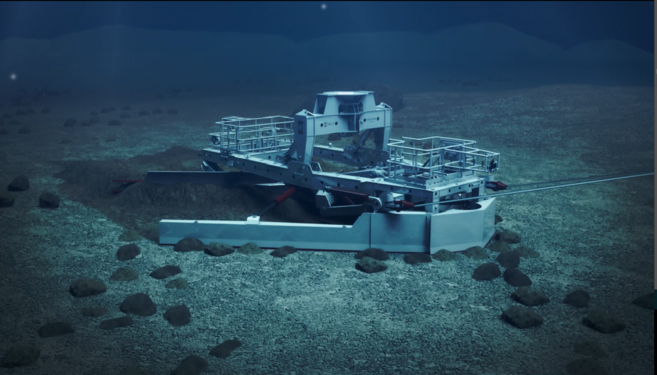
Before route engineering could begin, design parameters needed to be established with consideration for the capabilities of the equipment intended for boulder clearance and the digging of the cable trenches. The PLP240, engineered alongside Vattenfall and Osbit specifically for this project, would be able to achieve a clearance corridor of 16 m, remove boulders up to a maximum of 2 m in width and make cable turns on a 50 m radius.
The UTROV Grab was confirmed as being able to pick a boulder that was a maximum of 2.5 m in length and weighed a maximum of 10 tonnes, as long as two opposing arms could safely close around it. This meant that boulders greater than 2.5 m in length but under 2.5 m in width, or vice versa, could still be picked if they weighed less than 10 tonnes.
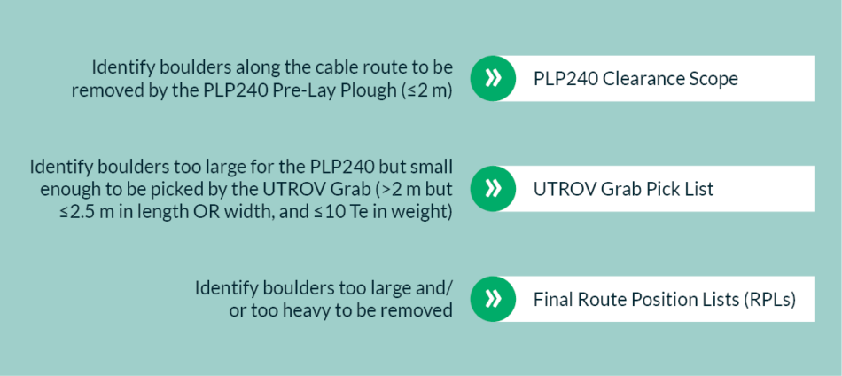
The ultimate goal of the boulder analysis work was to identify where on the cable routes the PLP240 would be able to clear boulders, where the UTROV Grab would be able to pick them, and where any remaining boulders too large for either of those activities would be left, requiring an amendment of the cable route itself. The process was iterative, with the cable route designed with all boulder and bathymetry data collated from within the PLP240’s 16 m cable corridor analysed, and the cable route adjusted based upon the results. This process was repeated until all immovable boulders were avoided and all other boulders could be ploughed or picked, which would then provide the team with the final cable routes.
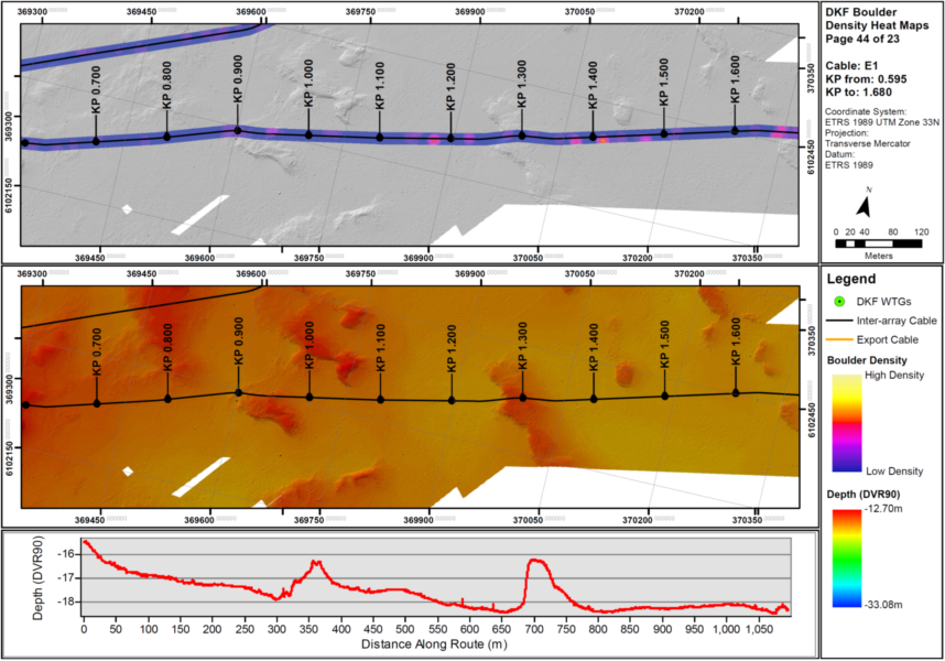
To achieve the final boulder listing, the findings from the route survey provided by Vattenfall – which incorporated side scan sonar and multibeam data – had to be refined in order for the route engineering team to only see those boulders which fell within the parameters of the PLP240’s clearance corridor. A 16 m buffer was added around the initial cable route position lists (RPLs), in accordance with the width of the PLP240’s blade, and spatial intersection was conducted to highlight the auto-picked survey targets (boulders) that fell within the buffer. These boulders were then analysed and categorised by their size and mass to determine the clearance method required.
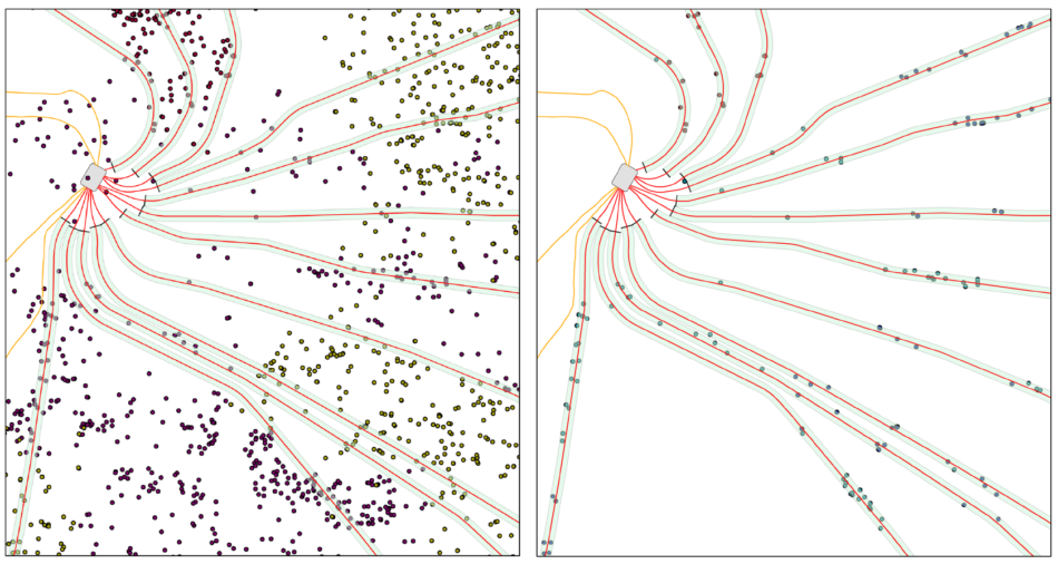
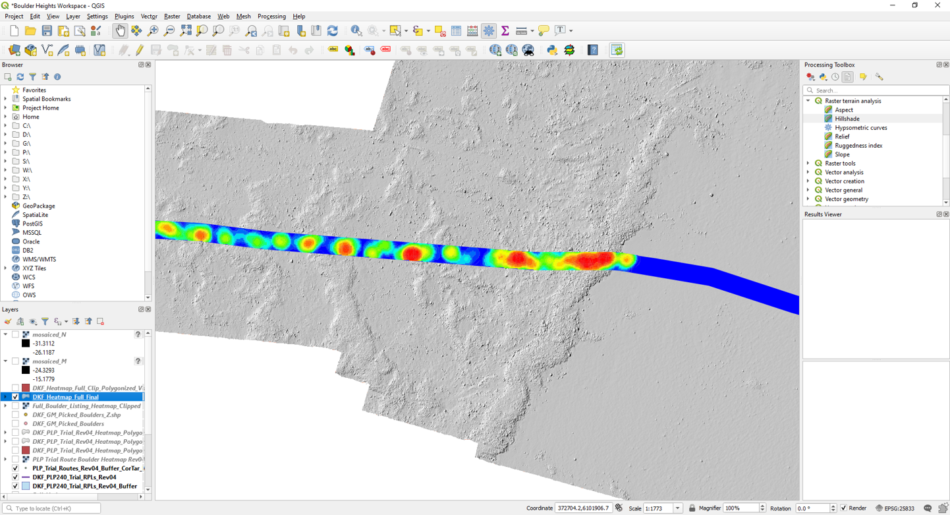
A significant number of boulders in the corridor were deemed too large to be removed by the UTROV Grab, however the auto-picking software that generated the original listing misidentified some clusters of small boulders as large, singular boulders. High-res bathymetry of the site was therefore inspected in order to clarify the findings and reclassify those which had been miscategorised.
Once the recategorisation was complete, the few immovable boulders that remained were routed around and avoided by the PLP corridor. With the final routes engineered, the final boulder listing was established resulting in a full boulder pick list for the grab and a list of boulders for the PLP240 to clear.
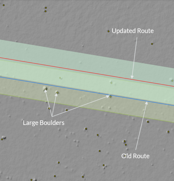
This detailed analysis led to a boulder risk mitigation strategy based primarily upon avoidance of larger or heavier stones whilst retaining routes which maximised the burial potential and protection for the cables. The inter array cable routes also had to avoid the potential unexploded ordinance (pUXO) targets identified by a thorough UXO survey campaign.
A series of additional tasks were also completed by the OceanIQ team in support of the project, which were as follows:
In total, the route engineering and boulder clearance work on the Danish Kriegers Flak project took almost 2 years to complete and afforded the team a great deal of experience that positively influenced the project and will be invaluable to future route engineering work too.
The investigative work completed by the OceanIQ team has enabled all 72 inter array cable routes to be successfully engineered and the cable trenches to be ploughed. Global Offshore are currently installing the cables on site and completing the cable pull ins at the turbines, with OceanIQ continuing to support, as required, to ensure the ongoing success of the project.
Francis Dick joined the Global Marine Group in 2018 and works as a Route Engineer for OceanIQ. Find out more about Francis on LinkedIn.
OceanIQ’s highly knowledgeable route engineering department provide a wide range of services designed to support subsea cable networks across the lifecycle of each system. Head to the Route Engineering services page to see how OceanIQ can ensure the longevity and viability of your system, whether it be in the initial planning phases or in an existing system that is currently operational.
This article was published in pages 82-84 of PES Wind 41 Magazine